Speed-Modulated Ironing: High-Resolution Shade and Texture Gradients in Single-Material 3D Printing
DOI: https://doi.org/10.1145/3654777.3676456
UIST '24: The 37th Annual ACM Symposium on User Interface Software and Technology, Pittsburgh, PA, USA, October 2024
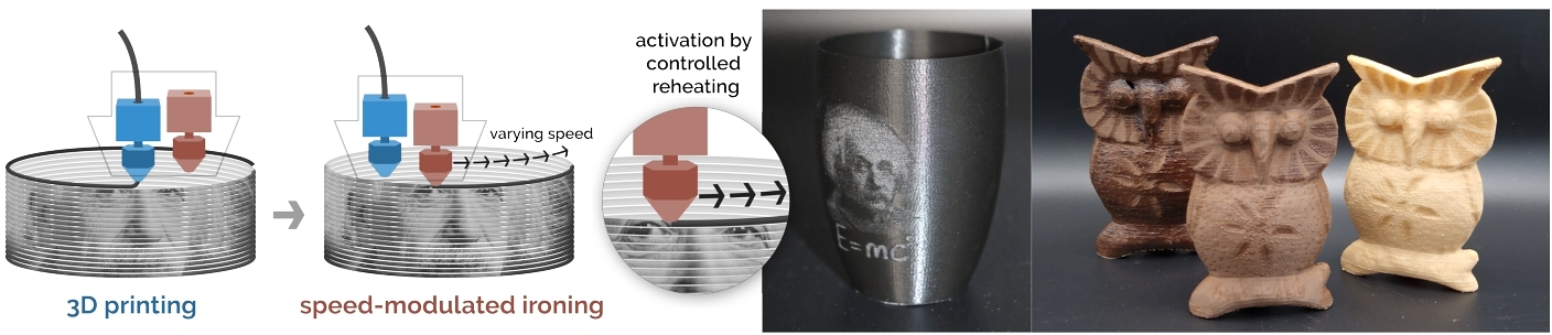
We present Speed-Modulated Ironing, a new fabrication method for programming visual and tactile properties in single-material 3D printing. We use one nozzle to 3D print and a second nozzle to reheat printed areas at varying speeds, controlling the material's temperature-response. The rapid adjustments of speed allow for fine-grained reheating, enabling high-resolution color and texture variations. We implemented our method in a tool that allows users to assign desired properties to 3D models and creates corresponding 3D printing instructions. We demonstrate our method with three temperature-responsive materials: a foaming filament, a filament with wood fibers, and a filament with cork particles. These filaments respond to temperature by changing color, roughness, transparency, and gloss. Our technical evaluation reveals the capabilities of our method in achieving sufficient resolution and color shade range that allows surface details such as small text, photos, and QR codes on 3D-printed objects. Finally, we provide application examples demonstrating the new design capabilities enabled by Speed-Modulated Ironing.
ACM Reference Format:
Mehmet Ozdemir, Marwa AlAlawi, Mustafa Doga Dogan, Jose Francisco Martinez Castro, Stefanie Mueller, and Zjenja Doubrovski. 2024. Speed-Modulated Ironing: High-Resolution Shade and Texture Gradients in Single-Material 3D Printing. In The 37th Annual ACM Symposium on User Interface Software and Technology (UIST '24), October 13--16, 2024, Pittsburgh, PA, USA. ACM, New York, NY, USA 13 Pages. https://doi.org/10.1145/3654777.3676456
1 INTRODUCTION
Material extrusion 3D printing is becoming a widespread technology that is being used for an increasing number of applications. With the ultimate goal of fabricating 3D objects in one go, researchers and makers aspire towards the ability of 3D printers to process parts with multiple properties [2]. Printing parts with different colors, textures, and other visual properties and doing so at a high resolution is essential for many applications.
For multi-color or multi-property printing, the standard workflow is to use multiple materials, each with their own properties [12]. However, in this approach, a material can only be assigned to a discrete region in the 3D print, making it impossible to assign values "in-between" and to fabricate graded transitions. Other methods include a pre-processing of the filament prior to 3D printing [14] or mixing materials in the nozzle [30], all of which require additional hardware or printer modifications. Alternatively, approaches based on using the temperature response of some specific filaments have been proposed. These include foaming filaments [19] and wood-filled filaments [16]. With these materials, heat can be used to locally vary the resulting properties during printing. In existing work, the printing nozzle temperature is used to vary, for example, the color or roughness of the printed part. However, nozzle temperature cannot be rapidly changed, which significantly limits the resolution of the achievable property variations.
Eliminating the dependency on the slow nozzle temperature change and allowing high-resolution, fine-grained control of visual and tactile properties, we present Speed-Modulated Ironing. Our novel method works by using one nozzle of an unmodified dual-extruder 3D printer to lay down the filament and the second nozzle to control the temperature response by passing over the deposited layer, exposing it to varying levels of heat. The key idea that enables continuous property variations is to vary the heat the second nozzle applies by modulating its speed rather than the slow heating and cooling of the nozzle. The rapid changes in the applied heat also allow for high-resolution variations in the resulting properties. We present a design tool that implements Speed-Modulated Ironing, and a user interface that allows users to assign desired visual and tactile properties to 3D models, which, on export, are converted into 3D printing process instructions (gcode) for Speed-Modulated Ironing.
We discuss results from our technical evaluation that provide insight into how the ironing parameters, temperature, and speed influence the achieved variations in properties. Finally, we provide application examples that demonstrate the new design capabilities enabled by Speed-Modulated Ironing, such as single-material objects with varying color shade, translucency, and tactile texture across their surface.
Our main contributions are summarized as follows:
- a fabrication technique, called Speed-Modulated Ironing, that enables continuous programming of temperature-responsive filaments to provide fine-grained control over visual and tactile properties of objects 3D-printed with a single material.
- a design tool that allows the assignment of these properties to 3D models for Speed-Modulated Ironing.
- a set of applications with continuously varying properties created with our design tool.
- a technical evaluation of how ironing parameters relate to achievable details and property variations.
2 RELATED WORK
Our work is related to multi-property FDM 3D printing, leveraging material response to 3D printing parameters, and modified 3D printing strategies.
2.1 Multi-Property FDM 3D Printing
3D printed objects that result from FDM 3D printing typically only have a limited number of material properties since each extruder can only be assigned a single material at a time. To overcome this limitation, researchers investigated how to fabricate gradients of different materials. For instance, researchers showed how to create gradient color by interleaving black and white filaments to create grayscale images [11, 24]. A different approach to fabricating gradients of different materials is to use custom hardware that feeds multiple filaments into a single mixing nozzle at varying rates [7, 25]. Since different print temperatures and print speeds required by different materials limit what materials can be mixed together, Takahashi et al. proposed to pre-fabricate a filament that consists of individual segments made from different materials [15, 29]. While this allows for a more diverse range of materials, the filaments need to be prefabricated for each individual 3D-printed object. Addressing this issue, Mosaic provides a custom hardware add-on that can assemble a filament from different filament spools on the fly depending on the 3D model that is being printed1. However, the properties of the 3D-printed object are still limited to the number of spools the hardware can process in one print job.
2.2 Leveraging Material Response to 3D Printing Parameters
The 3D print quality, surface finish, and mechanical properties of FDM printed parts are dependent on process parameters (e.g., nozzle temperature, print speed) and slicing settings (e.g., layer height, line width, infill density, and type) [6, 23]. Thus, these parameters allow controlling certain properties of the printed part, such as strength and toughness [10, 27], or shape memory [20, 26].
While the previously mentioned works use common filaments to program material properties, there are also filaments with additives that can be triggered by heat to obtain a significant and visible response. For example, filaments with wood particles become darker when printed at a higher temperature and have been used to vary color shade in a print [16]. Another category is foaming filaments [9, 18]. These filaments contain a foaming agent that, when extruded, expands the material volume into a closed-cell foam structure. The properties of the 3D printed foam depend on the heat applied, which, when varied, can produce various visual and haptic [19], as well as mechanical properties [3, 4, 21]. While researchers have presented strategies to apply such filaments at different states in 3D printed objects, all of the strategies rely on using the relatively slow temperature change of the printing nozzle. This leads to limited freedom and resolution in locally varying properties. We discuss these challenges in more detail in Section 3.
2.3 Modified 3D Printing Strategies
To expand the capabilities of 3D printers, researchers have developed a number of custom 3D printing strategies. For instance, WirePrint [17] moves the print head along the z-axis to create toolpaths that 3D print the objects as a wireframe for fast prototyping. Furbrication [13] uses rapid movements of the print head to create hair-like structures by leveraging the stringing properties of the filament. DefeXtiles [5] uses different rates of under-extrusion to produce textile-like structures with varying flexibility within 3D printed objects. Similarly, Velocity Painting uses under-extrusion due to rapid print speed changes to create visual patterns on the object's surface [32].Expressive FDM [28] modifies the height of the extruder in conjunction with the amount of deposited material, which results in different printed patterns, thereby forming various haptic structures. All of these works have in common that they enable new 3D printing capabilities without modifying the 3D printing hardware. Our work is in line with these related papers in that we leverage the existing unmodified hardware and embedded control systems to fabricate parts in an unconventional and new way. Unique in our approach is that we separate the printing from the programming step to achieve the desired visual and haptic properties, expanding the capability of the 3D printer.
3 Method: Speed-Modulated Ironing
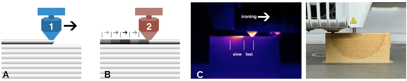
Speed-Modulated Ironing is a novel fabrication technique to achieve high-resolution shade and texture gradients by continuous fine-grained programming of temperature-responsive filaments. In our method, every layer is first printed and then re-heated by a second nozzle, which irons over the layer at a constant temperature but at precisely controlled speeds, see Figure 2. By separating the printing step from the programming step, we address the inability of a printing nozzle to change temperature rapidly. This allows us to locally vary the applied heat with precision and thus, to change properties of temperature-responsive filaments at an unprecedented resolution. In this section, we introduce the used materials, discuss the challenges of fine-grained temperature control, explain the working principle of our method, and present our theoretical model of ironing-induced heating.
3.1 Temperature-Responsive Filaments
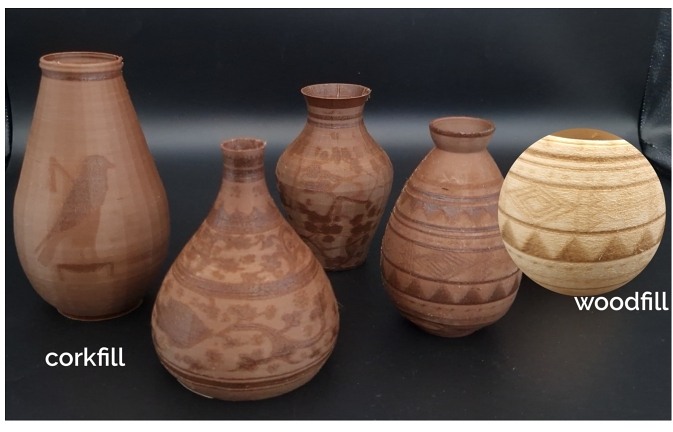
Our method utilizes the ability of some materials to obtain varying color shade, texture, and translucency when exposed to different levels of heat. In this paper, we present our work on three off-the-shelf 3D printing filaments; however, in principle, our approach can be used for other temperature-responsive materials as well. The first filament is a foaming filament, which contains a foaming agent that causes the filament to convert into a closed-cell structure when heat is applied. The higher the applied heat, the more the foam expands, leading to larger cells. The cells in the foam structure scatter light, resulting in a brighter color appearance and increased opacity. In addition, the cells result in a coarser tactile feel of the surface. The type of foaming filament used in this work is LW-PLA2. As the second and third material, we use PLA filled with wood fibers (Woodfill3) and with cork fibers (Corkfill 4) respectively. The last two filaments have a comparable temperature response, they obtain a progressively darker color shade when exposed to higher temperatures due to pyrolysis [16].
3.2 Challenge: Fine-Grained Control of Applied Heat
Our goal is to be able to create 3D prints with local property variations that are continuous and have a high resolution. While the temperature-response of filaments has been used before to locally vary appearance or other properties in 3D prints [16] [19], none of the existing methods is capable of reproducing high-resolution shade and texture details, since they rely on changing the printing nozzle temperature, which is very slow and challenging to control. For example, to obtain significant color change in Woodfill filament, the nozzle temperature must vary between 195° C and 300° C, which takes tens of seconds on most 3D printers. Since rapid changes in nozzle temperature are not possible, existing approaches rely on segmenting the 3D geometries into discrete regions, each printed at one temperature. The temperature changes are then done in-between printing the segments. Furthermore, the nozzle needs to be purged frequently when a filament that has been exposed to a high temperature is present in the nozzle, but the next part needs to be printed at a lower activation level. This results in long print times, and increased material waste. The segmentation imposes significant limits to the achievable resolution, as every segment is printed in a separate path, losing the continuous nature of extrusion 3D printing. The smoothness of graded transitions is also limited since gradients are divided into discrete steps and truly graded transitions are only possible in the z-direction of printing, the only case where the nozzle has sufficient time to achieve the required temperature. These limitations make the approaches that change printing nozzle temperature unsuitable for our purpose.
3.3 Programming Through Ironing
Working principle: We separate the 3D printing and re-heating for programming into two consecutive steps using an unmodified dual-nozzle 3D printer. The first nozzle is dedicated to the primary task of 3D printing the filament at a relatively low nozzle temperature that does not cause any temperature response of the material (see Figure 2 a). The second nozzle is empty (i.e., does not have any filament loaded into it) but is used for programming the properties by re-heating the already printed layer of material. The re-heating is done by moving the empty heated nozzle over the print while slightly touching, "ironing", the top of the printed layer. The temperature increase in the layer triggers a temperature response of printed material, such as change in color shade. The separation of the 3D printing and programming into two steps allows us to leverage the accurate motion control of the printing head since the speed of the ironing nozzle can be rapidly and precisely changed within a layer, unlike nozzle temperature. We keep the ironing nozzle temperature constant and modulate the applied heat through variations in ironing speed (see Figure 2 b). Slow ironing causes the layer to heat up more than when ironing at a faster speed (see Figure 2 c). We choose to use separate nozzles for printing and ironing. Doing both steps with the same nozzle is impractical as it requires long temperature changes at every layer. This increases print time significantly and exposes residual material in the nozzle to high temperatures for prolonged times, which will likely clog the nozzle. We derive the name of our method from the known concept in 3D printing, "ironing", where the top surface of a 3D model is smoothed by a nozzle at a constant speed.
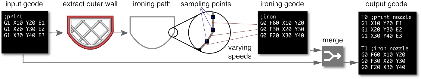
Ironing workflow: The main input to our workflow is the gcode of a sliced geometry for a single-nozzle 3D print prepared by the user. Gcode instructions for the ironing by the second nozzle are inserted into this input gcode while all 3D printing instructions and features, such as inner walls, infills, and support structures, remain unchanged. This workflow also preserves the user preferences of slicing, machine, and material-related settings for 3D printing. A schematic overview of the workflow is shown in Figure 3.
Since we are interested in the color shade and textures of 3D objects in this work, our method applies the ironing step only to the outer contour in each layer. For each layer of the 3D print, we extract the contour geometry of the outer wall from the input gcode. To this contour, we apply sampling points at a distance that we tested as short as 0.2mm. For each point, we then sample the intended property value (color shade, texture, translucency). The property values can be defined via an image, such as the color texture image of a 3D mesh file, or the user can project an image onto a 3D geometry directly in our tool (see Section 4).
Each sampled value, for example, target color shade, is then mapped to an ironing speed that will yield the required re-heating and, therefore, corresponding color change in the material. Using these modulated speeds, we create ironing toolpaths and insert these into every layer of the input gcode, together with the printer instructions for the nozzle changes. The final gcode file can be sent to the 3D printer for fabrication.
Ironing parameters: For each of the used materials, we determined the ironing parameters that yield the desired results. We aimed for a maximum difference in the property (color shade, texture, translucency) while keeping the structural and 3D detail integrity of the 3D printed shape. For example, a too-high ironing temperature or too-slow ironing speed may be able to trigger a response of the material but at the same time damage the printed structure. Possible damages include an unintended roughening of the surface or even holes in the printed part. This means that the ironing parameters need to be well-balanced. The main parameters we investigated were ironing temperature, ironing speed range, and ironing height. Table 1 presents the ironing parameters we use in our method.
| nozzle temperature [° C] | min speed [mm/s] | max speed [mm/s] | |
| LW-PLA | 300 | 1 | 60 |
| Woodfill | 325 | 1.5 | 10 |
| Corkfill | 325 | 1 | 20 |
We tested different ironing nozzle heights, which were measured as the distance from the printed layer. When the ironing nozzle is too high, there is too little to no contact with the printed layer, which leads to insufficient re-heating and, therefore, no property change. An ironing nozzle that is too low will "dive" into the printed layer, causing visible damage. The best results were obtained when there was no height difference, i.e., the tip of the ironing nozzle was at the same height as the top of the printed layer. This requires a well-calibrated z-offset of the two nozzles in the 3D printer. Many modern 3D printers have an auto-bed leveling feature that can be used to address this issue.
3.4 Theoretical Model
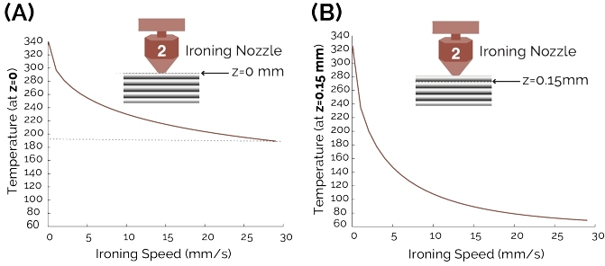
The relationship between the ironing speed and the temperature obtained in the material has shown to be highly non-linear in our initial tests. To be able to control the temperature response of the material accurately, a better understanding of this relationship was needed. We therefore developed a theoretical model for ironing-induced heating. We use the reached material temperature as a proxy for color change in our model. For Woodfill, the relationship between temperature and color change has shown to be linear within a temperature range of 200° C and 300° C [16].
We model the system as a 1D conductive heating problem of a semi-infinite region with one-sided heating. The ironing nozzle acts as the heat source and is in close proximity or direct touch with the printed layer. The printbed is an adiabatic surface of fixed temperature. Since convection to air is minimal when ironing is actively occurring, we ignore its contribution in our model. Consequently, the heat transfer equation for our model is:
(1)
where T is the temperature of the material, z is the (vertical) distance from the heat source (ironing nozzle), t is the time, and α is the thermal diffusivity of the material. We solve the governing heat transfer differential equation (Equation 1) as a function of z and t:
(2)
where "erfc(x)" is "1-erf(x)" (error function). The boundary conditions are T(z, 0) = Tbed, constant heat flux at surface, and T(∞, t) = Tbed. Under these conditions, using constant values for PLA (k = 0.1W/mK, h = 50W/m2K, α = 10− 7 $\frac{m^{2}}{s}$) [22, 31],and substituting t with Dnozzle/Viron (where Dnozzle = 1.3mm), the exact governing solution for the heat transfer equation is expressed as:
(3)
where T is the material temperature (°C), z is the distance from the heat source (mm), and Viron is the nozzle's ironing speed (mm/s).Tbed is the printbed temperature, which is held constant at 60°C, and Tiron, is the ironing nozzle's temperature.
Figure 5 shows the modeled maximum temperature of the material as a function of different ironing speeds, assuming an ironing nozzle temperature of 340°C.
We validate our model with experimental data in Section 6 and use the insights of the non-linear relationship between ironing speed and locally obtained temperature for the mapping of the desired property change to ironing speed in our tool, as discussed in Section 4.
4 Speed-Modulated Ironing Tool
We developed a tool with a user interface that allows users to apply our method in their 3D printing workflow5. It provides an accessible way for makers to create locally varying shades, textures, and translucency with a single material using their unmodified 3D printers. In the recommended mode, the tool currently supports the three materials we have used in this paper without the need to modify any settings. For advanced users or for users who want to apply the method to not-yet-tested materials, we also provide the option to change the ironing parameters and other settings of our tool. The tool and the interface are implemented in Rhinoceros 3D Grasshopper and can be considered as a gcode post-processor since it generates and adds the computed ironing printer instructions to existing gcode files.
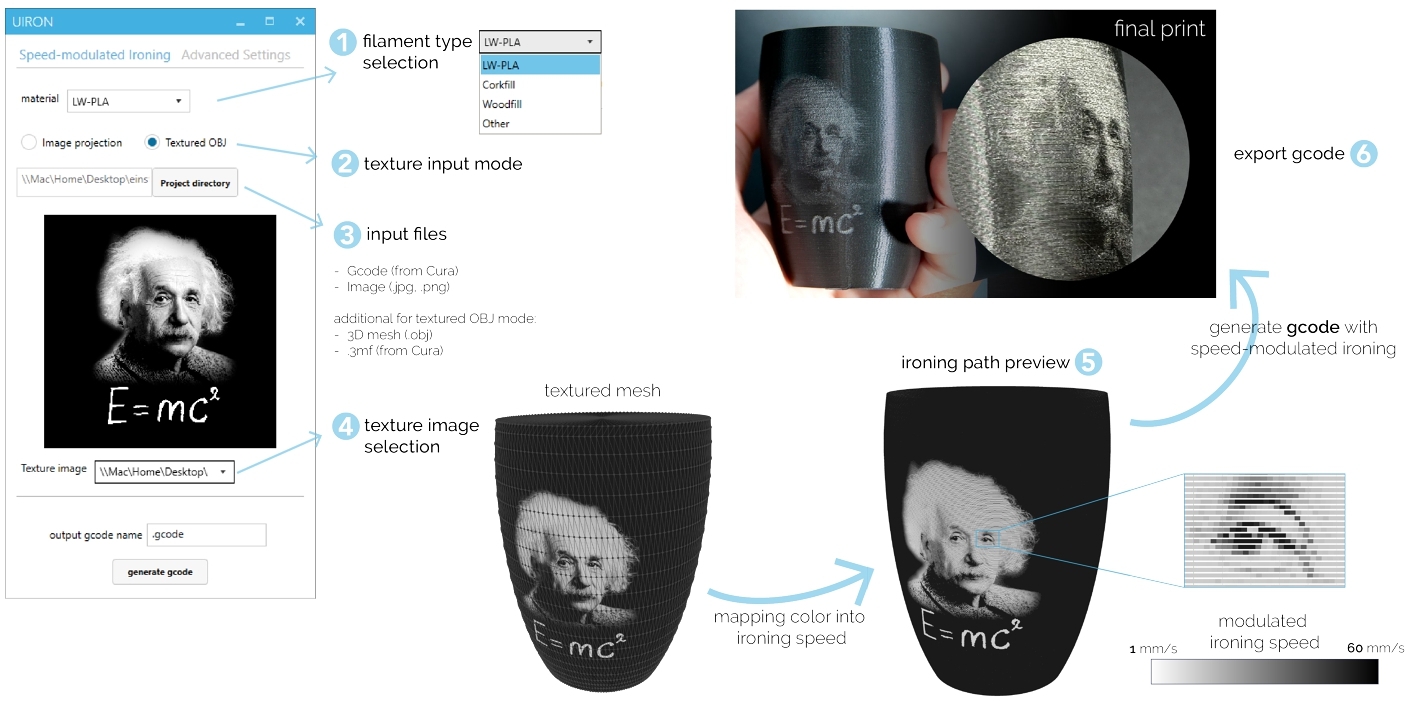
File preparation and gcode generation: The user interface and the steps to use the tool are presented in Figure 4.
Prior to using the tool, the user needs to slice the geometry for their printer with standard slicer software. Our current implementation assumes the file is sliced using Cura6 slicer. We share recommended Cura settings along with the Speed-Modulated Ironing tool. The first step in our tool is to choose the material to be used, which defines the ironing settings (step 1 in Figure 4). This is followed by selecting the texture input mode, which is either image projection or textured OBJ mode (step 2 in Figure 4). Next to the pre-sliced gcode, the required input files depend on the selected input mode. The textured OBJ mode, requires a textured mesh file (in the Wavefront OBJ file format) and a 3MF file (exported from Cura along with the gcode). All the input files need to be stored in a project directory, and this folder has to be selected on the interface (step 3 in Figure 4). The texture or projection image should be included in the same folder, which can be selected and viewed on the interface (step 4 in Figure 4).
Our design tool reads all the documents from the folder and processes them as follows: First, the gcode file is used to extract the outer wall toolpaths for every layer, which are used as the contour path for the ironing. This contour is subdivided into segments of 0.2mm to get the sampling points (Figure 3). In the textured OBJ mode, the mesh is automatically aligned with the gcode by using the transformation matrix from the 3MF file. Then, using the UV mapping values from the OBJ mesh, for every sampling point, the color values from the OBJ texture file are extracted and converted to grayscale values. Since the relationship between ironing speed and color change is not linear, for every material a lookup table was generated using equation 5 and table 2. The lookup table is used to assign every sampling point with the ironing speed that was found to achieve the required color change. In the image projection mode, the grayscale values of a user-selected 2D image are projected through the 3D model over one axis using parallel projection. Then, for every sampling point, the corresponding grayscale value from the 2D image is used to obtain the ironing speed using the same lookup tables as in the textured OBJ mode.
Finally, choosing the generate gcode on the tool, the print-ready output file is saved to the project directory. The user can see the preview of the generated file (step 5 in Figure 4), where the preview shows the gradients on the object surface. Depending on the chosen material, the preview shows the expected color values that will be obtained in the print. After exporting the gcode (step 6 in Figure 4), the file can be sent for fabrication. Figure 4 also shows the final printed object in comparison to the preview. The combination of material-specific mapping of the ironing speeds and high sampling rate, the tool allows the fabrication gradients that appear smooth and linear to the human eye.
Advanced mode: For users to experiment with the process or test additional materials, we provide advanced settings in the tool. These include both ironing and printing settings. In the ironing settings, the users may control the sampling length (resolution of the speed variations), ironing temperature, speed interval, and nozzle Z-offset. Lowering the sampling length provides finer texture details while resulting in a longer processing time and a larger output file. The other settings here can be fine-tuned for new materials. We also provide the option to change several print settings that are also material-dependent. For instance, standby temperature (printing nozzle temperature while inactive) and retraction settings are helpful to avoid material oozing out of the printing nozzle while ironing with the second nozzle.
5 APPLICATIONS
We demonstrate applications that are uniquely enabled by our method to vary the color shade, translucency, and tactile texture.
5.1 Color Shade
Our approach offers precise control over shade variations within 3D-printed objects. For example, textures, decals, and text on 3D models allow for personalized designs. By carefully controlling the re-heating process, printed aesthetic patterns can be created, adding additional artistic appeal to objects such as vases, mugs, or decorative sculptures. Figure 6 shows a series of vases with different decorative patterns applied to the surface.
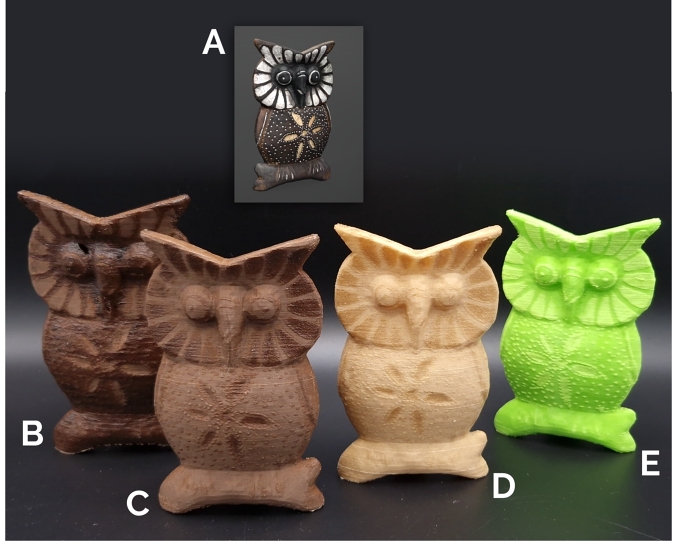
Our method can also be used to fabricate 3D-scanned objects. A textured mesh of a color-scanned owl figurine 7 was imported into our tool (Figure 7 a). The model with the texture details was reproduced using Corkfill filament,, (Figure 7 b and c), Woodfill filament (Figure 7 d), and green foaming filament (Figure 7 e).
These examples illustrate the capability of our method of enhancing 3D prints with decorative or functional visual features.
5.2 Translucency
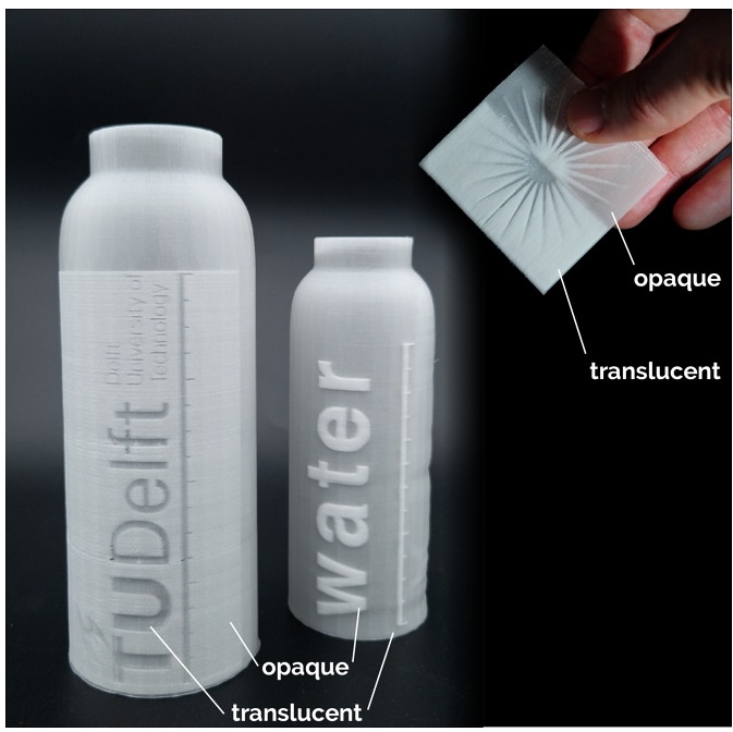
Translucency is a desirable property in various objects, and our method enables the creation of 3D-printed objects with regions of varying translucency. As an example of local translucency differences, Figure 8 shows transparent liquid containers with opaque design features printed using "natural color" LW-PLA.
5.3 Tactile Texture
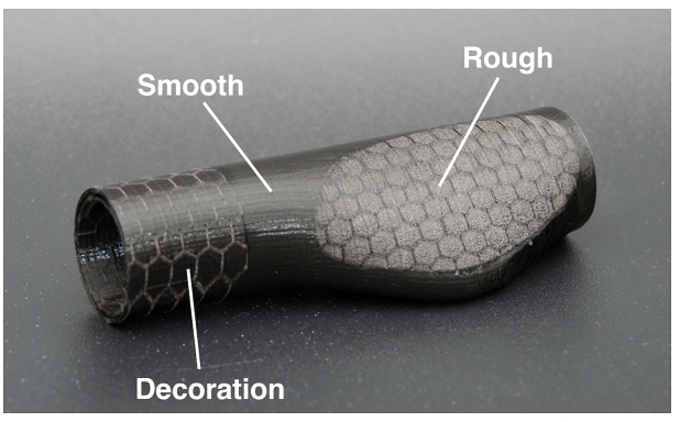
Texture plays a crucial role in the tactile functionality and user experience of objects. Our method enables the incorporation of diverse textures into 3D-printed objects. It allows customization of texture variations according to custom comfort or personal requirements, making it suitable for a wide range of applications. This includes textured handles for tools and appliances or ergonomic grips for sports equipment, e.g., the bike handle example in Figure 9.
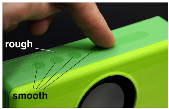
Figure 10 shows a speaker enclosure with touch buttons which are smoother to the touch compared to the rest of the housing. These areas also visually signal the tactile, "touchable" nature of the buttons. This part was printed using regular PLA (i.e. without special additives) and is, therefore, an example of our method being applied using a commonly used printing material.
6 TECHNICAL CHARACTERIZATION
Our technical evaluation determines achievable color shade difference as a function of ironing speed on three types of filament: Woodfill, Corkfill, and a foaming filament (LW-PLA, Black). We also characterize the performance of our method in its capability to reproduce fine shade details on the surface of objects.
6.1 Color Difference
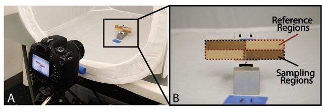
We 3D printed samples of 80mm x 20mm to which a 2x2 rectangular grid of different regions was applied. Two of these were the reference regions that were ironed at a constant high speed at which no significant re-heating, and therefore no color change, occurs. The other two regions were ironed at lower speeds and varied per sample; these were the sampling regions (Figure 11 b). All samples were printed on an Ultimaker S5.
The samples were placed inside a diffusion box (Figure 11 a) for controlled lighting conditions and photographed with a DSLR camera. We used the CIELAB [8] color space to measure the colors of the samples.
To gauge the color difference our method can achieve, we use Δ E as the metric. Δ E (Equation 4) represents the Euclidean distance between two colors in CIELAB color space. A Δ E less than or equal to 1.0 is considered to be a non-perceivable color difference for the human eye [8].
The conversion to CIELAB and the calculation of the Δ E were done in an interactive Matlab script that we developed. Since our samples have two sampling regions and two reference regions within a single print, we calculate Δ E with respect to each reference, then report the global average (Figure 11 b). Because the color difference values are all measured relative to the reference zones, possible variations in lighting conditions are eliminated.
(4)
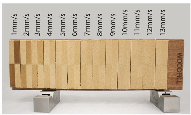
Woodfill Filament: We prepared 13 samples with fixed printing nozzle parameters (200°C printing temperature, 0.15 mm layer height, 0.4mm line width, no infill, wall-count 2). The ironing temperature was 340 °C, and the ironing speed was varied from 1mm/s to 13 mm/s for the sampling regions. All reference regions had an ironing speed of 40 mm/s.
The results of the printed samples are illustrated in Figure 12.
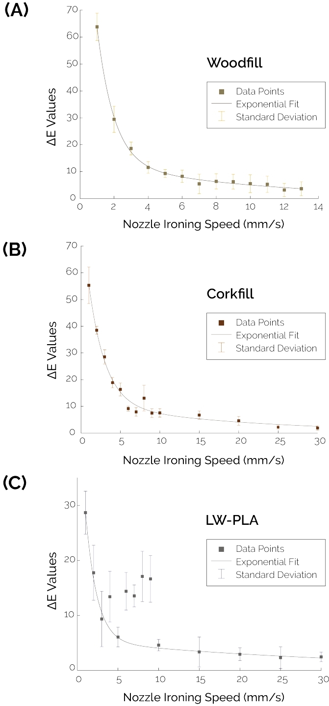
As shown in Figure 13, as the ironing speed increases, the Δ E value decreases exponentially until it plateaus. The maximum Δ E was measured in the 1mm/s sample with a value of 63.8 ± 5.06.
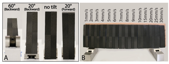
Because of the glossiness of the non-foamed material, the viewing angle and lighting direction affect the perceived color difference within the prints. For instance, in Figure 14 a, the test pattern is clearly distinguishable at no tilt. However, when the same sample is tilted forward, it appears darker, and when tilted backward, it appears lighter. Within our evaluation, we selected the orientation that yielded a stable color difference with minimal reflections, which is a vertical orientation with no tilt.
Finally, the range of speeds tested was from 1mm/s to 30 mm/s for the sampling regions, and 40 mm/s for the reference regions. The printed results are illustrated in Figure 16, where we generally observe an exponential decay of contrast values as a function of ironing speed. The maximum Δ E attained at this orientation under non-directional lighting is 28.66 ± 3.91 at 1mm/s ironing speed. The outliers between 4mm/s and 9mm/s can be attributed to the sample's changed glossiness at both ironed and reference regions, resulting in higher contrast or Δ E values, as can be seen in Figure 14 b.
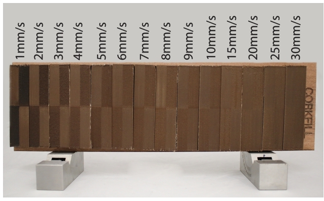
Similar to the measurements of the Woodfill and foaming filaments, the Δ E values for Corkfill decrease exponentially with an increasing ironing speed (Figure 13). The maximum Δ E value for Corkfill was found to be 55.33 ± 6.81, obtained by ironing at 1mm/s.
Measured Characteristic of Δ E: To get a characteristic description of the measurements in an equation, we first normalize the measured Δ E. We can describe the relationship between the measured Δ E and ironing speed in mm/s with the exponential equation:
(5)
where v is the velocity in mm/s. For normalized Δ E, the constant values we found for the three filaments are given in Table 2. All the values are within a $95\%$ confidence bound, while in the case of foaming filament, this confidence bound excludes the outliers at ironing speeds of 4,6,7,8 and 9 mm/s.
| a | b | c | d | |
| Woodfill | 2.283 | -1.115 | 0.318 | -0.239 |
| Corkfill | 0.191 | -0.076 | 1.347 | -0.482 |
| LW-PLA | 0.144 | -0.086 | 1.828 | -0.734 |
Validation of the theoretical model: The experimental results correspond to the general trend we expect from our theoretical model, which is an exponentially decaying graph as a function of increasing ironing speed.
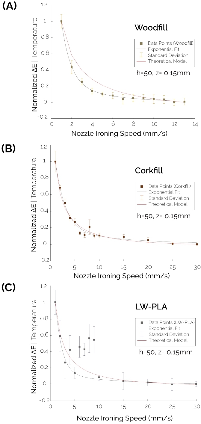
By normalizing the data from the theoretical model between 1 and 0, we are able to compare the characteristic relationship between ironing velocity and measured Δ E and the modeled ironing velocity as a function of temperature at z= 0.15mm (layer height).
Figure 16 b shows this result for Corkfill filament. The theoretical model fits the experimental data well with a maximum normalized error of 0.0672 (i.e., 6.72$\%$ of the max value) and an average error of 0.0168 (i.e., 1.68$\%$ of the max value). We also generally conclude from the closeness of fit between the experimental and theoretical models how the relationship between the normalized temperature values and normalized Δ E values is linear.
Using the same method for the Woodfill printed samples, we find that the experimental model fits the theoretical model generally but with a larger error margin in comparison to the Corkfill model (max error of 0.16 or 16$\%$, and average error of 0.06 or 6$\%$). This is also true for the foaming LW-PLA filament with a max error of 0.1329 or $13.29\%$, and a mean error of 0.035 or $3.5\%$) excluding outliers.
6.2 Detail Reproduction
To evaluate the capability of our method to reproduce a variety of visual features and texture designs, we prepared samples that test rapid variations in color shade, thin features, and gradient transitions of color. All tests were carried out for LW-PLA, Woodfill, and Corkfill filaments.
Detail and gradient testing: A 60mm x 60mm x 60mm cube was designed, and a test image was applied to each of the four vertical faces. The test images are illustrated in Figure 17 a. The first test image is a QR code, which tests a practical application of rapid spatial transitions with significant color differences. The second image aims to evaluate the ability to produce smooth gradients. The third tests thin light lines on a dark background and dark lines on a light background at different angles. Finally, the last image evaluates rapid transitions between minimum and maximum reheating.
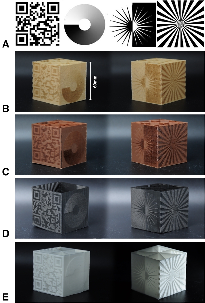
All samples were printed successfully with Woodfill, Corkfill, black LW-PLA, and natural LW-PLA; see Figure 17 b, c, d, e. The prints allowed a closer inspection of the performance of our method with the test images. For all materials, the QR codes were of sufficient quality and contrast to be directly readable by a regular smartphone camera. Also, the circular gradient came out with an even and smooth transition with all materials. The main edge case is the test of thin lines printed with Woodfill. For these specific features, it might be necessary to reconsider the ironing parameters (i.e. nozzle temperature and speed). However, for Corkfill and LW-PLA, the lines were produced well and showed clear sharp transitions irrespective of line orientation.
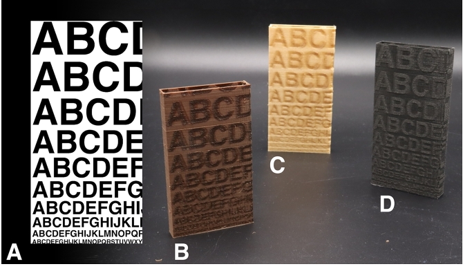
Text legibility: To evaluate at which sizes legible text can be reproduced, samples of 50mm x 100mm were created, to which an image with text was applied. The text size varied from 40pt down to 5pt; see Figure 18 a. The resulting samples are shown in Figure 18 b, c, and d. We found that our method can reproduce the larger font sizes on all three materials. For LW-PLA, the smallest readable font size was 9pt, while for Woodfill and Corkfill, the smallest readable font size was 14pt.
7 DISCUSSION
Applicability: The printed results indicate that our proposed method can fabricate 3D prints with textures that have a high spatial resolution and smooth color gradients that are generally unavailable to FDM 3D printing. This allows a wide variety of visible features to be added to 3D printed parts, expanding the current capabilities and applicability of FDM printing.
Our method does not require any 3D printing hardware modifications. Also, we show that our method can be applied to parts that were sliced with machine-specific and user-defined settings without changing them. As a result, all printing features (e.g. infills, support structures) can remain unaltered. This means that integration into existing slicers would not require significant changes in the core algorithms or printing strategy.
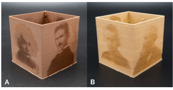
Printing time and material use: Compared to other common approaches for multi-color FDM prints, our method can lead to shorter print times and less material use. As an indicator of printing time, the cup with the Einstein image (Figure 4) took 2h 30m, while the original (uncolored) cup takes 1h 30m to complete. Comparing this to multi-material printing on the same machine, a two-color print of the cup with a similar image results in a printing time of 3h 50m. A Bambu Lab X1-Carbon (4-material printer) yields a printing time of 14h 30m for the cup and uses more than 10 times the volume of material due to frequent material switching and consequent purging. An approach that uses nozzle temperature variation for color change [16] documents up to a 10-fold increase in printing time and double the material use compared an uncolored model.
Energy consumption: Printing the reference cup with our method required 0.29kWh, while the dual-material print used 0.42kWh. The same cup as a regular single material (uncolored) print uses 0.13kWh. While our method uses more energy compared to printing without applying color, for a reference print (Figure 4) it uses less energy than common dual-material printing on the same machine. Furthermore, the existing methods have difficulty achieving the resolution and gradients of our method because their texture details rely on the extrusion of the material itself.
8 LIMITATIONS AND FUTURE WORK
In this section, we discuss the limitations of our approach and avenues for future work.
Specific printer used: Our research primarily utilized Ultimaker printers (models 3, S3, S5, and S7) to explore the responsiveness of three distinct filament types to varied reheating through ironing. During this exploration, we also focused on the processing of gcode tailored for Ultimaker’s Cura slicer. The adaptation of our technique for other FDM printers requires an understanding of each printer's operation and specific gcode formatting, particularly in determining layer heights and extracting contours for ironing. However, the fundamental principles of Speed-Modulated Ironing hold across different hardware, which would facilitate the method's broader applicability with appropriate adjustments for individual printers. Future work will also explore the integration of our approach into existing slicers (i.e., rather than using a separate processing tool), and a detailed examination of other printer-specific parameters, such as acceleration, to further optimize print time and resolution.
Extending the design space: While our current work has focused on the visual and tactile enhancements possible through Speed-Modulated Ironing, we envision its utility in programming not just surface-level properties but also in manipulating mechanical, acoustic, and even shape-morphing characteristics inherent to the material itself. The exploration of foaming filaments illustrates this potential, where localized control over mechanical properties [1] could also impact the way how objects are designed and utilized.
The current version of our design tool processes only the outer surface of the object. We plan to implement the possibility of ironing the whole layer (including the inner regions and top/bottom layers) in the future version. Furthermore, by experimenting with a diverse range of materials, we hope to further expand the design space. As an indication, in Figure 10, we showed that our method can also be applied to vary the visual and tactile properties a regular PLA filament. This example hints at the potential of Speed-Modulated Ironing for future applications.
9 CONCLUSION
In this work, we introduced Speed-Modulated Ironing, a novel method that expands the capabilities of single-material 3D printing by enabling high-resolution control over visual shade and tactile texture gradients. Using one nozzle to 3D print and the second nozzle to reheat printed areas at varying speeds, we achieve intricate activation of temperature-responsive filaments, such as Woodfill, Corkfill, and foaming filaments, in a single fabrication process. Using our software tool, users can achieve high-resolution fabrication of objects with graded shades, textures, and translucency, without necessitating multiple materials or complex hardware modifications.
We demonstrated the capability of our approach to create objects with fine textures and graphics using a single material, the resolution of which we analyzed in our technical evaluation. For future work, we will further adapt our workflow to program the properties of the printed object not just on the outer surface but on the interior as well. Applying this to the interior is especially relevant when locally modifying mechanical properties. We hope that our work represents a step toward a more versatile, expressive, and sustainable form of 3D printing and will enable further explorations in temperature-responsive materials.
ACKNOWLEDGMENTS
We extend our gratitude to Joris van Dam for his invaluable technical assistance, and to Ultimaker for providing equipment and offering essential insights into printer functionalities.
REFERENCES
- 2020. Testing colorFabb varioShore TPU - Foaming 3D printing filament. https://www.cnckitchen.com/blog/testing-colorfabb-varioshore-tpu-foaming-3d-printing-filament
- Patrick Baudisch and Stefanie Mueller. 2017. Personal Fabrication. Foundations and Trends® in Human–Computer Interaction 10, 3–4 (May 2017), 165–293. https://doi.org/10.1561/1100000055
- A. R. Damanpack, André Sousa, and M. Bodaghi. 2021. Porous PLAs with Controllable Density by FDM 3D Printing and Chemical Foaming Agent. Micromachines 12, 8 (Aug. 2021). https://doi.org/10.3390/MI12080866 Publisher: Multidisciplinary Digital Publishing Institute (MDPI).
- Mohammadreza Lalegani Dezaki, Mahdi Bodaghi, Ahmad Serjouei, Shukri Afazov, and Ali Zolfagharian. 2022. Soft Pneumatic Actuators with Controllable Stiffness by Bio-inspired Lattice Chambers and FDM 3D Printing. Advanced Engineering Materials (Dec. 2022). https://doi.org/10.1002/ADEM.202200797 Publisher: John Wiley & Sons, Ltd.
- Jack Forman, Mustafa Doga Dogan, Hamilton Forsythe, and Hiroshi Ishii. 2020. DefeXtiles: 3D Printing Quasi-Woven Fabric via Under-Extrusion. In Proceedings of the 33rd Annual ACM Symposium on User Interface Software and Technology. ACM, 1222–1233. https://doi.org/10.1145/3379337.3415876
- A. García-Collado, J. M. Blanco, Munish Kumar Gupta, and R. Dorado-Vicente. 2022. Advances in polymers based Multi-Material Additive-Manufacturing Techniques: State-of-art review on properties and applications. Additive Manufacturing 50 (Feb. 2022), 102577. https://doi.org/10.1016/j.addma.2021.102577 Publisher: Elsevier.
- Anthony Garland and Georges Fadel. 2015. Manufacturing Functionally Gradient Material Objects With an Off the Shelf 3D Printer: Challenges and Solutions. In Volume 4: 20th Design for Manufacturing and the Life Cycle Conference; 9th International Conference on Micro- and Nanosystems, Vol. 4. American Society of Mechanical Engineers. https://doi.org/10.1115/DETC2015-47841 Issue: 11.
- B. Hill, Th. Roger, and F. W. Vorhagen. 1997. Comparative analysis of the quantization of color spaces on the basis of the CIELAB color-difference formula. ACM Transactions on Graphics 16, 2 (April 1997), 109–154. https://doi.org/10.1145/248210.248212
- Karun Kalia, Benjamin Francoeur, Alireza Amirkhizi, and Amir Ameli. 2022. In Situ Foam 3D Printing of Microcellular Structures Using Material Extrusion Additive Manufacturing. ACS Applied Materials & Interfaces 14, 19 (May 2022), 22454–22465. https://doi.org/10.1021/acsami.2c03014 Publisher: American Chemical Society.
- Jivtesh B Khurana, Shantanab Dinda, and Timothy W Simpson. 2017. Active - Z printing: A new approach to increasing 3D printed part strength. In Solid Freeform Fabrication 2017: Proceedings of the 28th Annual International Solid Freeform Fabrication Symposium - An Additive Manufacturing Conference, SFF 2017. 1627–1644.
- Tim Kuipers, Eugeni Doubrovski, and Jouke Verlinden. 2017. 3D hatching: linear halftoning for dual extrusion fused deposition modeling. In Proceedings of the 1st Annual ACM Symposium on Computational Fabrication(SCF ’17). Association for Computing Machinery, New York, NY, USA, 1–7. https://doi.org/10.1145/3083157.3083163
- Nahyun Kwon, Himani Deshpande, Md Kamrul Hasan, Aryabhat Darnal, and Jeeeun Kim. 2021. Multi-ttach: Techniques to Enhance Multi-material Attachments in Low-cost FDM 3D Printing. In Proceedings of the 6th Annual ACM Symposium on Computational Fabrication(SCF ’21). Association for Computing Machinery, New York, NY, USA, 1–16. https://doi.org/10.1145/3485114.3485116
- Gierad Laput, Xiang ’Anthony’ Chen, and Chris Harrison. 2015. 3D Printed Hair: Fused Deposition Modeling of Soft Strands, Fibers, and Bristles. In Proceedings of the 28th Annual ACM Symposium on User Interface Software & Technology(UIST ’15). Association for Computing Machinery, New York, NY, USA, 593–597. https://doi.org/10.1145/2807442.2807484
- Eammon Littler, Bo Zhu, and Wojciech Jarosz. 2022. Automated Filament Inking for Multi-color FFF 3D Printing. In Proceedings of the 35th Annual ACM Symposium on User Interface Software and Technology(UIST ’22). Association for Computing Machinery, New York, NY, USA, 1–13. https://doi.org/10.1145/3526113.3545654
- Qian Lu, Aryabhat Darnal, Haruki Takahashi, Anastasia Hanifah Muliana, and Jeeeun Kim. 2022. User-Centered Property Adjustment with Programmable Filament. In Extended Abstracts of the 2022 CHI Conference on Human Factors in Computing Systems(CHI EA ’22). Association for Computing Machinery, New York, NY, USA, 1–6. https://doi.org/10.1145/3491101.3519864
- Kongpyung (Justin) Moon, Jaeseong Yi, Valkyrie Savage, and Andrea Bianchi. 2024. 3D printed pyrography: Using wood filament and dynamic control of nozzle temperature for embedding shades of color in objects. Additive Manufacturing 83 (March 2024), 104064. https://doi.org/10.1016/j.addma.2024.104064
- Stefanie Mueller, Sangha Im, Serafima Gurevich, Alexander Teibrich, Lisa Pfisterer, François Guimbretière, and Patrick Baudisch. 2014. WirePrint: 3D printed previews for fast prototyping. In Proceedings of the 27th annual ACM symposium on User interface software and technology(UIST ’14). Association for Computing Machinery, New York, NY, USA, 273–280. https://doi.org/10.1145/2642918.2647359
- Mohammadreza Nofar, Julia Utz, Nico Geis, Volker Altstädt, and Holger Ruckdäschel. 2022. Foam 3D Printing of Thermoplastics: A Symbiosis of Additive Manufacturing and Foaming Technology. Advanced Science 9, 11 (April 2022), 2105701. https://doi.org/10.1002/ADVS.202105701 Publisher: John Wiley & Sons, Ltd.
- Mehmet Ozdemir and Zjenja Doubrovski. 2023. Xpandables: Single-filament Multi-property 3D Printing by Programmable Foaming. In Extended Abstracts of the 2023 CHI Conference on Human Factors in Computing Systems(CHI EA ’23). Association for Computing Machinery, New York, NY, USA, 1–7. https://doi.org/10.1145/3544549.3585731
- Mehmet Ozdemir and Zjenja Doubrovski. 2024. Foam2Form: 4D Printing with Programmable Foaming. In Extended Abstracts of the 2024 CHI Conference on Human Factors in Computing Systems(CHI EA ’24). Association for Computing Machinery, New York, NY, USA, 1–8. https://doi.org/10.1145/3613905.3650869
- Ajinkya Pawar, Gilles Ausias, Yves Marie Corre, Yves Grohens, and Julien Férec. 2022. Mastering the density of 3D printed thermoplastic elastomer foam structures with controlled temperature. Additive Manufacturing 58 (Oct. 2022), 103066. https://doi.org/10.1016/J.ADDMA.2022.103066 Publisher: Elsevier.
- Lucas Pereira, Todd Letcher, and Gregory J. Michna. 2019. The Effects of 3D Printing Parameters and Surface Roughness on Convective Heat Transfer Performance. American Society of Mechanical Engineers Digital Collection. https://doi.org/10.1115/HT2019-3591
- Kumaresan Rajan, Mahendran Samykano, Kumaran Kadirgama, Wan Sharuzi, Wan Harun, and Md Mustafizur Rahman. 2022. Fused deposition modeling: process, materials, parameters, properties, and applications. The International Journal of Advanced Manufacturing Technology 2022 (Feb. 2022), 1–40. https://doi.org/10.1007/S00170-022-08860-7 ISBN: 0123456789 Publisher: Springer.
- Tim Reiner, Nathan Carr, Radomír Měch, Ondřej Št'ava, Carsten Dachsbacher, and Gavin Miller. 2014. Dual-color mixing for fused deposition modeling printers. Computer Graphics Forum 33, 2 (2014), 479–486. https://doi.org/10.1111/cgf.12319 _eprint: https://onlinelibrary.wiley.com/doi/pdf/10.1111/cgf.12319.
- Haichuan Song, Jonàs Martínez, Pierre Bedell, Noémie Vennin, and Sylvain Lefebvre. 2019. Colored Fused Filament Fabrication. ACM Transactions on Graphics 38, 5 (June 2019), 141:1–141:11. https://doi.org/10.1145/3183793
- Lingyun Sun, Yue Yang, Yu Chen, Jiaji Li, Danli Luo, Haolin Liu, Lining Yao, Ye Tao, and Guanyun Wang. 2021. ShrinCage: 4D Printing Accessories that Self-Adapt. In Proceedings of the 2021 CHI Conference on Human Factors in Computing Systems. ACM, New York, NY, USA, 1–12. https://doi.org/10.1145/3411764.3445220
- Yuxuan Sun, Wei Tian, Tao Zhang, Peng Chen, and Mujun Li. 2020. Strength and toughness enhancement in 3d printing via bioinspired tool path. Materials & Design 185 (Jan. 2020), 108239. https://doi.org/10.1016/j.matdes.2019.108239
- Haruki Takahashi and Homei Miyashita. 2017. Expressive Fused Deposition Modeling by Controlling Extruder Height and Extrusion Amount. In Proceedings of the 2017 CHI Conference on Human Factors in Computing Systems(CHI ’17). Association for Computing Machinery, New York, NY, USA, 5065–5074. https://doi.org/10.1145/3025453.3025933
- Haruki Takahashi, Parinya Punpongsanon, and Jeeeun Kim. 2020. Programmable Filament: Printed Filaments for Multi-material 3D Printing. In Proceedings of the 33rd Annual ACM Symposium on User Interface Software and Technology(UIST ’20). Association for Computing Machinery, New York, NY, USA, 1209–1221. https://doi.org/10.1145/3379337.3415863
- Riccardo Tonello, Md. Tusher Mollah, Kenneth Weiss, Jon Spangenberg, Are Strandlie, David Bue Pedersen, and Jeppe Revall Frisvad. 2024. Influence of the Printing Direction on the Surface Appearance in Multi-material Fused Filament Fabrication. In Computer-Aided Design and Computer Graphics, Shi-Min Hu, Yiyu Cai, and Paul Rosin (Eds.). Springer Nature, Singapore, 90–107. https://doi.org/10.1007/978-981-99-9666-7_7
- Lucie Trhlíková, Oldrich Zmeskal, Petr Psencik, and Pavel Florian. 2016. Study of the thermal properties of filaments for 3D printing. AIP Conference Proceedings 1752, 1 (July 2016), 040027. https://doi.org/10.1063/1.4955258
- Mark Wheadon. 2017. Velocity Painting. https://www.velocitypainting.xyz/blog/
FOOTNOTE
1 https://www.mosaicmfg.com/products/palette-3-pro
2 https://colorfabb.com/lw-pla-black
3 https://colorfabb.com/woodfill
4 https://colorfabb.com/corkfill
5 https://github.com/zjenjad/speed-modulated-ironing
6 https://ultimaker.com/software/ultimaker-cura/
7Owl Ornament Statue 3D Scan by 3DRstudio https://sketchfab.com/3d-models/owl-ornament-statue-3d-scan-a2ef1344af5143b9b0a214f969640a15

This work is licensed under a Creative Commons Attribution-NonCommercial International 4.0 License.
UIST '24, October 13–16, 2024, Pittsburgh, PA, USA
© 2024 Copyright held by the owner/author(s).
ACM ISBN 979-8-4007-0628-8/24/10.
DOI: https://doi.org/10.1145/3654777.3676456